(back)
Actuator
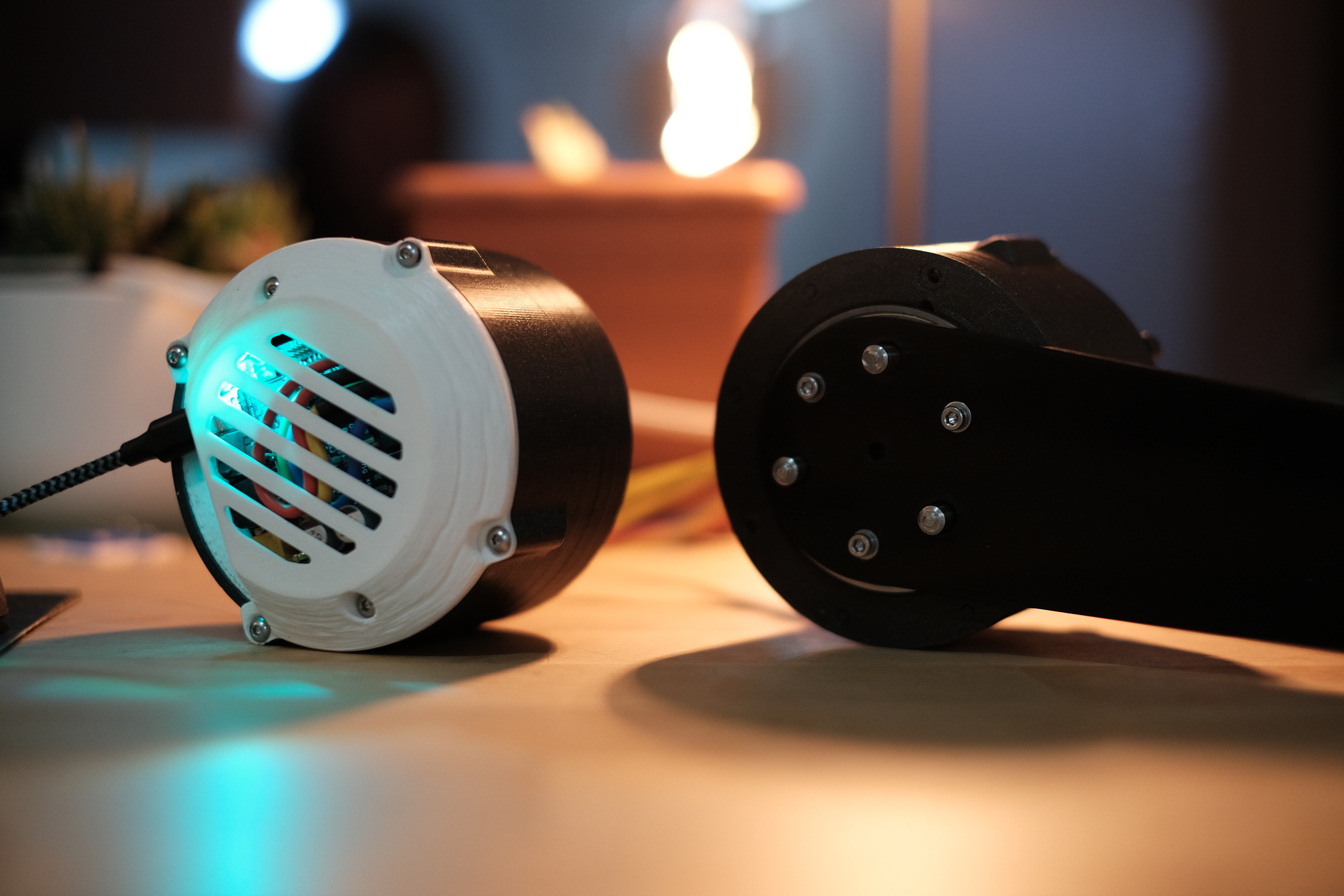
Two assembled V1 actuators
It is seemingly a rite of passage for any mechanically minded robotics engineer to want to design their own QDD actuator. As more mini-cheetah actuator clones appear on the market, this is becoming less of a practical need, but a learning project that touches on some of the fun parts of robotics hardware design. For extra brownie points, I decided to also design and write the firmware for the motor controller, as all the good drivers still seem to be $100+ (see the 50x50 drive page for some more information on that).
The result is a ~1kg, mostly 3D printed actuator with a 48V max, 105Kv BLDC, rated to 12Nm continuous and 35Nm peak. It's not the strongest, or most torque dense motor out there, but it was a ton of fun to design and most importantly it's ~1/4 of the cost of COTS alternatives. The motor frame was originally designed to be MJF Nylon, but the ASA prototypes held up well enough that I have not outsourced the printed frames yet.
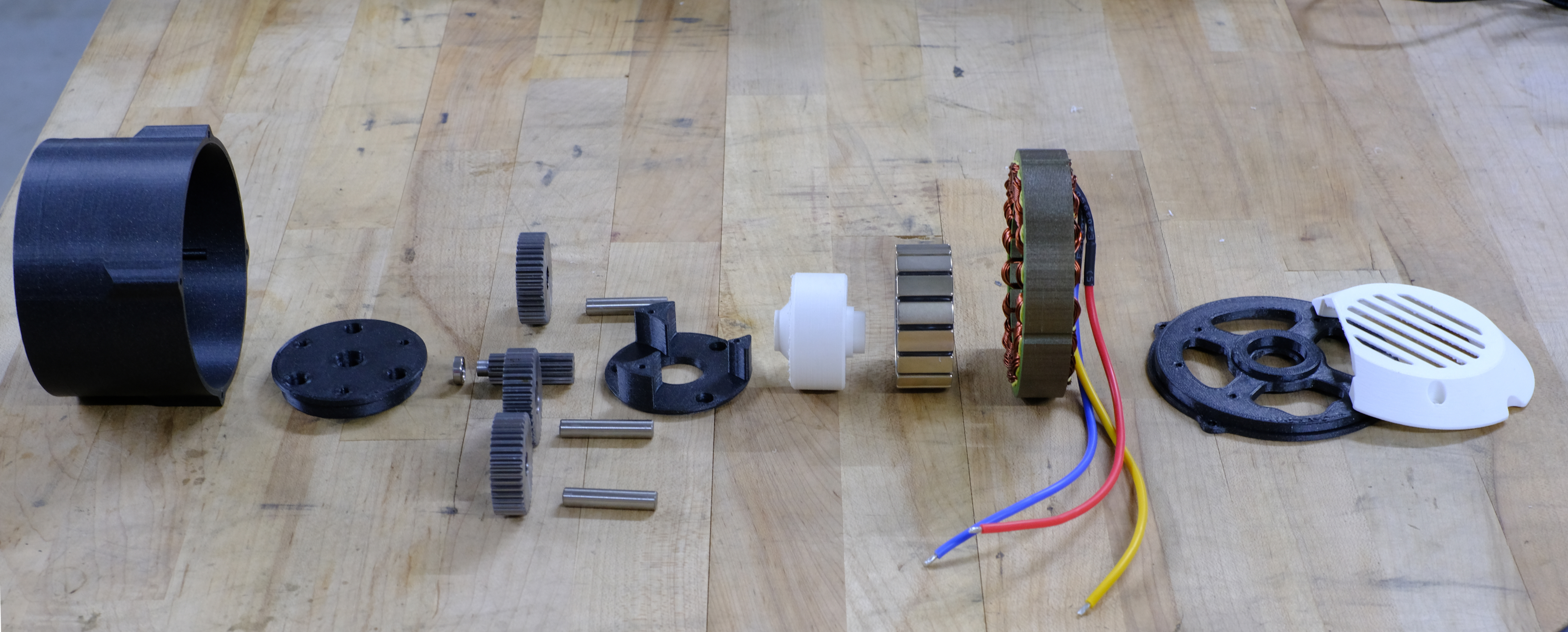
Exploded build for V1.1 of the actuator
So far I have made three of these actuators, and will be producing two more V3 versions soon. I will also be making two more actuators sans-reducer for the wheels on the half-scale handle. The V3 version will swap the in-runner for an out-runner to help increase torque density and reduce cogging torque. Additionally, I will be more of a stickler about gear tolerances in an effort reduce backlash (other than time-delays and sticktion, I have rediscovered that backlash is arguably the worst controls gremlin to fight).
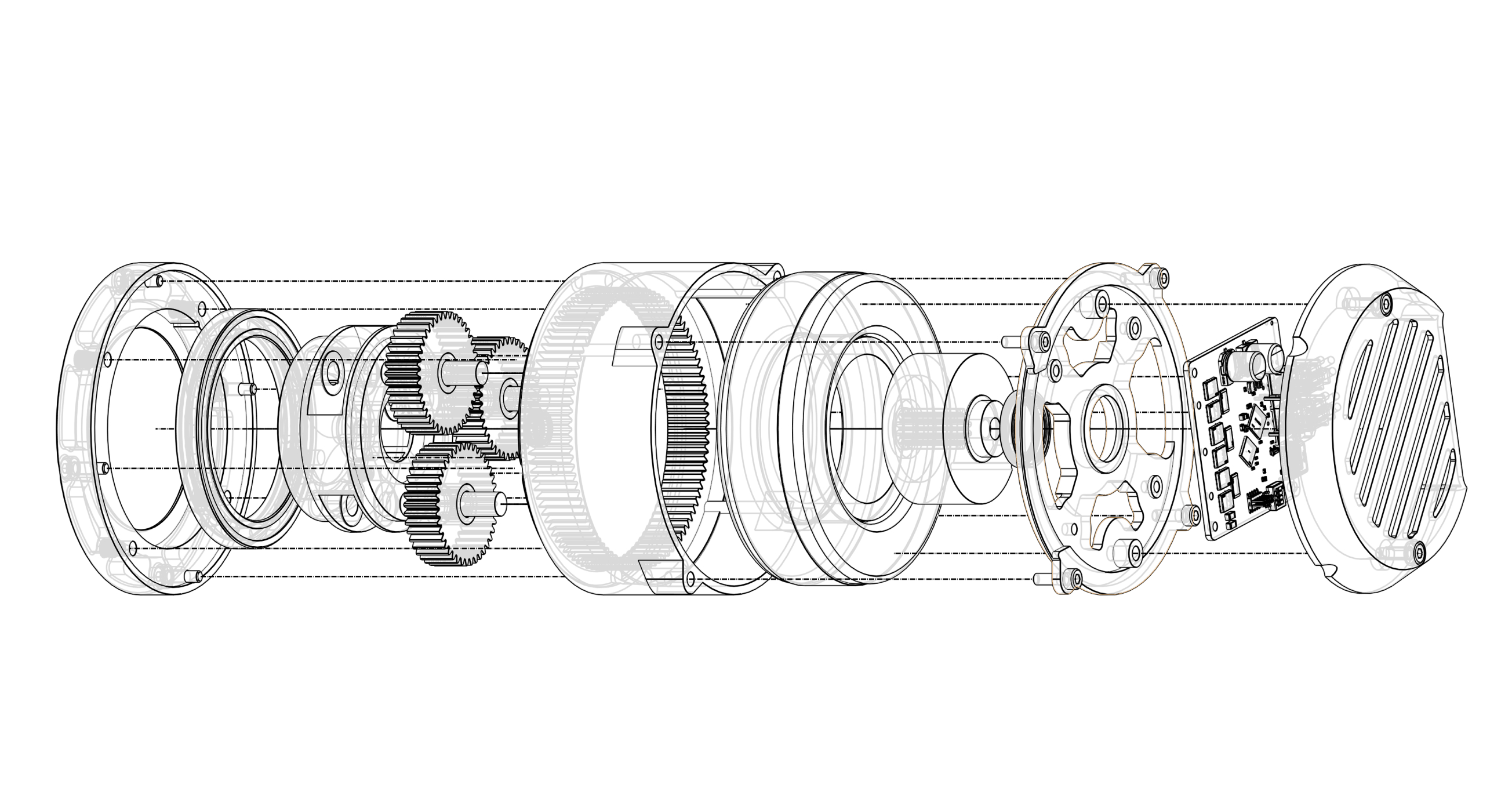
Exploded cad for V2 of the actuator
Much to the surprise/judgment of any mechanical engineer I tell, this drive uses a 3D printed ring gear. This cuts out a large amount of cost (if you know where to get steel ring gears capable of 30Nm for under $50, please tell me) while allowing for a more integrated design. I ran a few FEA sims assuming solid nylon and was fairly impressed at the performance. There are multiple teeth meshed per planet on the ring gear so the resulting force per tooth ends up being pretty reasonable. There are obviously wear concerns, but I have not seen any noticeable degradation and the nature of hobby projects means I might not run them enough to reach that point.
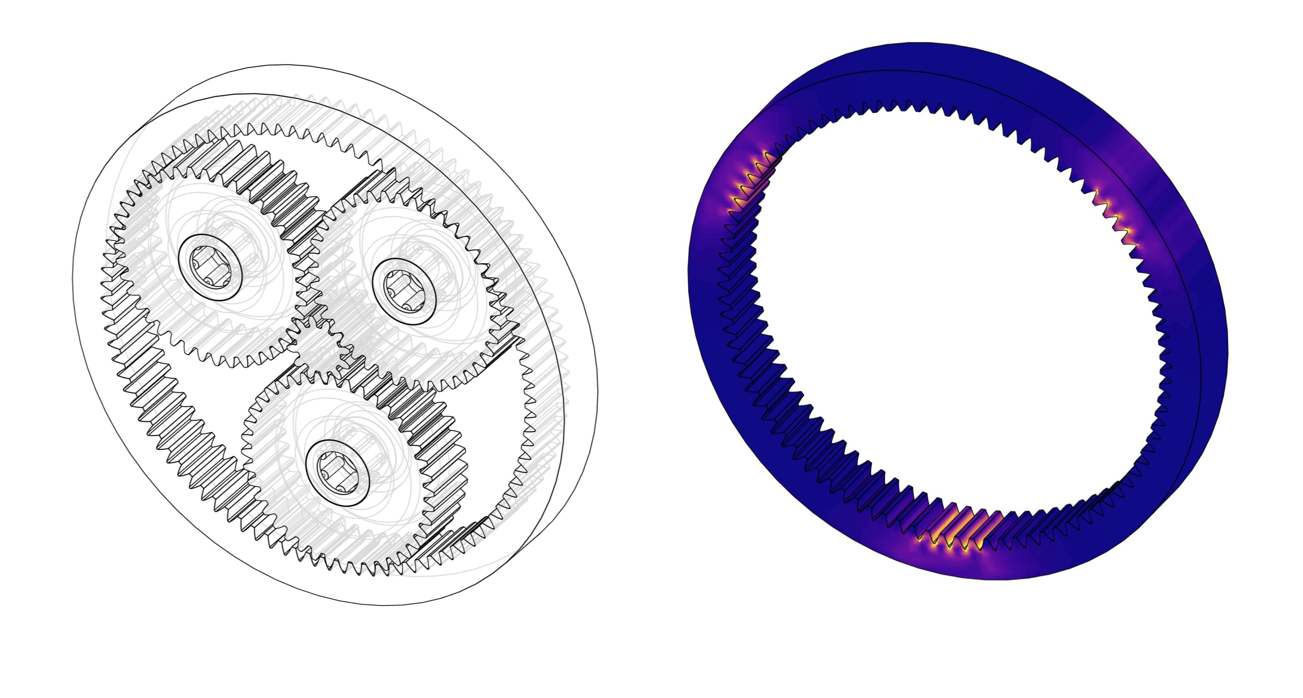
Static simulation of the tooth forces on the ring gear
Current-limited backdrivability testing